
Tutorials
Mapping

Mapping
Ted Boardman tedb@tbmax.com http://www.tbmax.com
Fall is fast approaching in New England…well, actually not so fast. Usually by the end of September the foliage is starting to show strong colors. This year is different. The colors develop when the sap drains from the leaves to the roots in preparation for the winter freeze, especially in the maple trees. But I presume the abnormally wet weather this summer has generated more sap and the ground is wetter so the moisture is staying in the leaves longer. This is pure speculation on my part, but the fact is only a few of the less healthy trees are showing signs of color. Chances are when the frosts start to hit the change over from green to flame colors will be rapid and spectacular.
If you haven’t seen a fall season in New England it is well worth the trip. There is something about being under a thick canopy of brilliant orange and red with the sun streaming through. It is a study in radiosity and translucency that can entertain for hours.
No, radiosity and translucency is not the topic of this month’s column. What I’ll cover is the process of applying multiple mapping coordinates to a single object and aligning the mapping to the various planes of an object. The technique is the same, except for some minor details in the appearance of the modifier stack, for versions of max and VIZ from 3 onward. I’ll do the example in 3ds max 4 just so that everyone can access the file.
Another small section at the end of the column will be a tip that can help make the 3D Boolean operations more reliable in VIZ 4 and max 5.
A topic that comes up frequently is that of applying more than one set of mapping coordinates to a single object. In this column I’ll walk through a typical architectural scenario, but the technique can be used for everything from racecars to characters.
You will open a scene that contains a small building typical of the type found in a European train yard. It is a single Editable Mesh object with a Multi/Sub-Object material assigned. The parts of the building, i.e. roof, walls, windows, etc have already been selected and assigned Material ID #’s so the materials are in the proper locations.
Note: The Material ID #’s could have been assigned in this exercise by selecting polygons with MeshSelect, then applying a Material modifier for each different material, but I have saved you a few steps.
In the Modify panel, Stack view, I have already selected the walls and applied a UVW Map modifier that is set to Box mode and gives the stucco exterior the size I want. There is also some graffiti in the material, but you will learn to use Map Channels at the end of the exercise to reveal the text. Figure 1 shows the building and the Multi/Sub-Object material in the Material/Map Navigator that has been assigned.
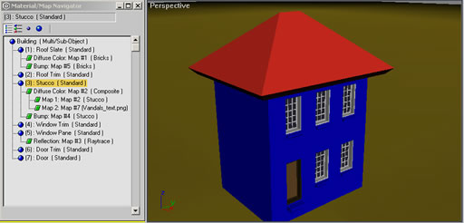
Figure 1: The building and the seven sub-materials that have been assigned with a Multi/Sub-Object material.
The file for this exercise was created in 3ds max 4 so that anyone using VIZ 4 and max 4 or higher can open the file.
Multiple Mapping Coordinates on a Single Object
The roof material is made up of Bricks map in the Diffuse and Bump slots to create a slate appearance. Your task will be to assign mapping coordinates to the planes of the hip roof so that the slates are projected onto the surfaces and sized correctly. You will use a combination of two maps for each plane. The MeshSelect will allow you to select only the polygon(s) you need and the UVW Map will actually orient and size the pattern correctly.
Note: The Bricks pattern has been set to 30 horizontal and 80 vertical bricks. This allows the Color and Fade Variance to be distributed over 2400 bricks to cut down on the repeating pattern that occurs when the default 3 by 8 or 24 brick pattern is used. The Gap setting for Bricks has also been adjusted for increased number of bricks.
Exercise: One Object, One Pattern, Multiple Planes with Mapping Coordinates
1. Open the file called Building.max and select the building in the Perspective viewport. In the Modify panel, notice the walls have been selected at Element sub-object level and a UVW Map modifier is added to the Element to size the Stucco map on the walls. You will now apply mapping to the different planes of the roof Polygons.
2. Open Material Editor and use Navigator to go to the Diffuse level for Roof Slate. Click on Show Map in Viewport. See Figure 2. The roof should be black.
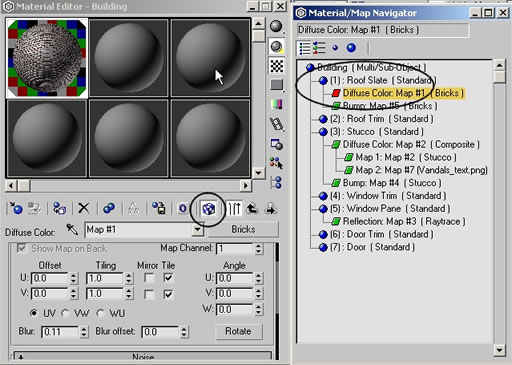
Figure 2: Use Material/Map Navigator to go to Roof Slate material, Diffuse Bricks level and turn on Show Map in Viewport.
3. In the Modifier List choose Mesh Select modifier. It does nothing but allow you to make object or sub-object selections. Go to sub-object Polygon and, in the Perspective viewport, pick the front roof planeIt will highlight red in the wireframe views and, if you turn on Shade Selected Faces, it will turn transparent red in the shaded viewport.
4. In the Modify panel, Modifier List, choose UVW Map. These mapping coordinates are only for the selected polygon from the Mesh Select below.
5. In the Modify panel, Parameters rollout, Alignment area, click the Normal Align button and, in the Perspective viewport, click and hold on the selected polygon and move the mouse a little. The UVW Map gizmo will flip to match the Face Normal of that polygon. See Figure 3.
 Figure 3: Using Normal Align in the UVW Map Parameters rollout, click and drag on the roof front polygon to align the gizmo with the surface.
6. In the Modify panel, Parameters rollout, enter 30’ (feet) in both Length and Width to size the gizmo. Click the Center button to center the gizmo on the plane. This is 2400 slates over a 30 foot by 30 foot area. Render the Perspective viewport to see the slates are correct on the front roof plane.
7. In the Modify panel, Modifier List, choose Mesh Select and go to Polygon sub-object level. Select the left end roof polygon to highlight it.
8. In the Modify panel, Modifier List, choose UVW Map modifier. Click the Normal Align button and click and drag on the selected polygon. Enter 30’ in Length and Width and click the Center button. You now have two planes with similar sized maps projecting to each respective plane. See Figure 4.
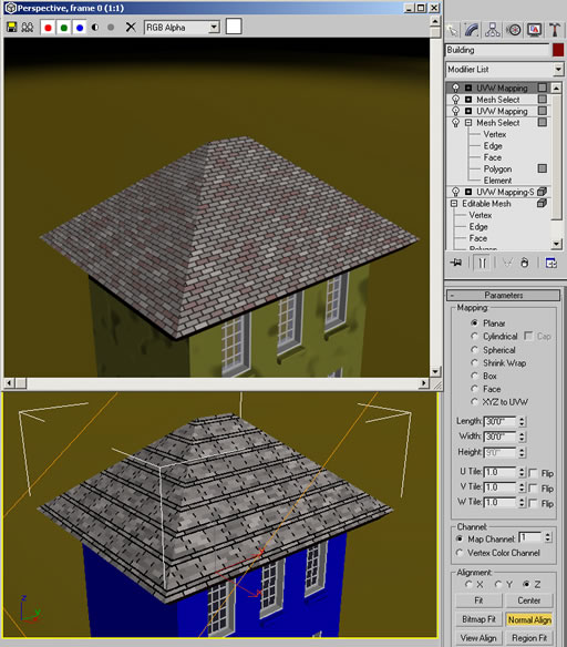
Figure 4: Apply another Mesh Select and UVW Map modifier and adjust the gizmo and size for the new roof plane.
9. Apply Mesh Select and UVW Map to the back roof plane, and again to the right roof plane.
10. After the final roof plane UVW Map adjustment is made apply another Mesh Select that is not in sub-object mode. This returns the stack to the whole object, not just a sub-object selection. The stack and roof should look similar to Figure 5.
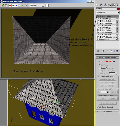
Figure 5: Whenever you have a sub-object selection levels, end the stack with a Mesh Select to return control to the whole object.
11. Render the Perspective viewport to see the roof slates and save the file.
Using Map Channels
The stucco material on the wall is actually a Composite map type with Stucco map and a Bitmap of some text that contains Alpha channel to make the black area of the map transparent. However, to get the Stucco sized correctly there is a UVW Map modifier (at the bottom of the stack) that is set to Box mapping type at 1” on each side. This projects the pattern in six directions to make it appear correct on all sides of the building.
The second level of the Composite, the text is using the same mapping coordinates so is restricted to an area of 1” square, much too small for you to see. You need to apply different mapping coordinates to the Bitmap text file to make it fit the side of the building. You will use Map Channels to match a particular map in the material to a UVW Map modifier sharing the same Map Channel number.
Exercise: Setting Map Channels for the Graffiti on the walls.
1. Open the file from last exercise and adjust Perspective viewport to look at the building obliquely from the left front. In the Modify panel, Modifier List, choose UVW Map to go on top of the stack. Render the scene to look similar to Figure 6. The Bitmap is using Map Channel 1 in the Material Editor. The new UVW Map uses Map Channel 1. All other UVW Map modifiers use the default Map Channel 1 also, but the top modifier in the stack wins as it is applied to the whole mesh object as determined by the Mesh Select below it.
Figure 6: The UVW Map modifier, set to Map Channel 1, controls mapping to the whole mesh. It messes up the roof slates and streaks the building with the text Bitmap.
2. You will correct this by setting both the text Bitmap and the top UVW Map modifier to use Map Channel 2. In the Material Editor, Bitmap level, Coordinates rollout, change the Map Channel number from 1 to 2.
3. In the top UVW Map modifier on the stack, Parameters rollout set it to affect only maps with Map Channel 2. Also, clear the Tiling checkboxes to keep the map from repeating over the surface. This is called Decal mapping.
4. In Parameters rollout, click the Normal Align button and click and hold on the left wall of the building to align the gizmo with it and resize the gizmo to 10’ in Length and Width.
5. Render the Perspective viewport and you will see the correctly sized Stucco with the word Vandals painted on the left wall. See Figure 7. Save the file.
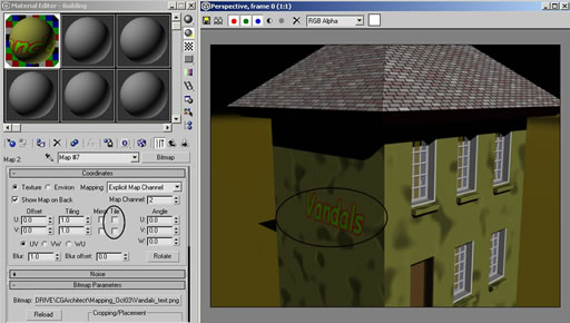
Figure 7: Clearing the Tiling checkboxes and setting the correct Map Channel allows you to map differently for different maps within the same material, in this case, as a Decal map.
You can also open a file named Building_Mapped.max that is an example of the same file already mapped, but with the names of the modifiers in the stack edited to reflect their function. This is a great method of keeping track of the logic behind modifiers and editing, especially in a office where there is collaboration between departments or team members.
Tip for Boolean Operations in VIZ 4 and 3ds max 5
There is a modifier in VIZ 4 and max 5 that can sometimes help make 3D Boolean operations more reliable and more efficient. I’ll use a simple example.
If you add a Subdivide modifier to an object you can determine the maximum distance between any two vertices on the model. As an example, I’ve created 2 boxes and 2 objects of 3 cylinders each.
On one of the boxes I’ve applied a Subdivide modifier with a Size of 4”, then converted the object to Editable Mesh. See Figure 8.
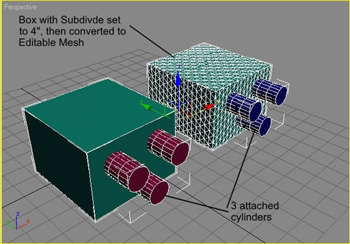
Figure 8: One Box with Subdivide, one without, both converted to Editable Mesh.
Using Boolean Subtract on both pair results in slightly different objects. You can see the long thin triangles created in the left box Boolean operation. These can cause much trouble with lighting, especially when it comes to using Radiosity. The box on the right only has to calculate the Boolean operation to the nearest vertex so is much more efficient and reliable.
However, the box on the right contains 2618 faces while the one on the left contains only 446 and you know how I can complain about too many unnecessary faces!
If I select the right box and apply an Optimize modifier the face count drops to 244. I can adjust the Max. Edge Length of the Optimize modifier to 20 to get rid of any long triangles created by the optimization and still only have 290 faces. See Figure 9.
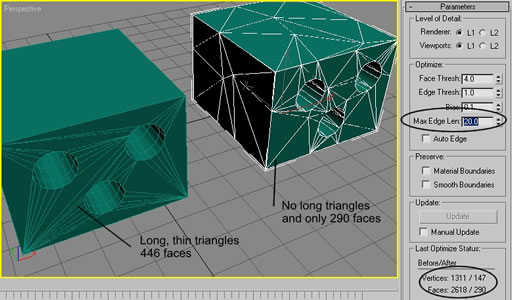
Figure 9: Adding an Optimize modifier and adjusting the Max. Edge Length eliminates any new long triangles and reduces the face count.
The result is a much more reliable Boolean operation with less total faces in the end. I would convert to Editable Mesh again to reduce any overhead caused by the Optimize modifier.
Figure 10 shows a landscape file made with Terrain that you can open and try to optimize it in the same manner. I applied a Subdivide modifier.
Warning: put the modifier on a small object in the scene first and set the Size to 500’ or more, then apply the modifier to the landscape. Otherwise it will use 1 meter Size on this large landscape and you could be waiting for a while for the calculations.
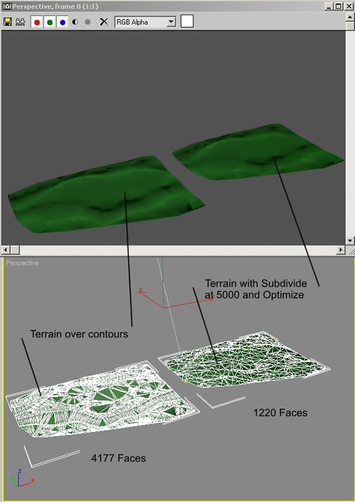
Figure 10: Contour lines with Terrain Compound Object on left. Same object with Subdivide modifier and Optimize modifier for a better mesh with fewer faces.
I then applied an Optimize modifier with a Max Edge Length of 5000. The face counts are significantly different, but the rendered images are practically identical. Converting to Editable Mesh would reduce overhead once you have the modifiers adjusted.
Summary
You learned how to apply different mapping coordinates to a single map used in different locations in a single object to place slate roofing on a hip roof. A Mesh Select and UVW Map modifier was added for each surface you needed mapping applied.
You also learned to adjust mapping coordinates for two maps in the same material by using separate UVW Map modifiers each set to a Map Channel to match the map being adjusted.
Using these two techniques can speed the mapping process in many situations. The process is the same for max 3 and VIZ 3 onward.
You also learned an application for the Subdivide modifier in VIZ 4 and max 5, primarily intended for use with Radiosity rendering, it can be used to clean up Boolean operations and complex mesh objects created with Terrain.
Good luck and have fun.
Ted
You must be logged in to post a comment. Login here.