Tutorials
Animation

Animation
Ted Boardman tedb@tbmax.com http://www.tbmax.com
Crocus and daffodils have finally started to appear. One of my favorite events of spring is just starting to develop; the emerging of the red and yellow buds on the various hardwood trees casts a slight color veil over the woods, especially when seen in direct sunlight or against the backdrop of evergreens.
With the ocean water still hovering around 40 degrees F it’s still not what you would call warm spring weather, but it’s great for getting out and driving around the New England countryside for a last glimpse of the houses back in the woods before the leaves restrict our vision to the edge of the road.
While on the topic of traveling around, I think I’ll use this column to review a few of the animation controllers and techniques that you may be able to use in your scenes. You might want to look back to my November 2002 column on using Ease Curves for more velocity control.
For each of the following exercises I’ll include two VIZ 4 files for your reference. One will be the base setup file and the other will be the completed exercise.
List Controllers
Adding an animation controller or constraint is easy and can be done in either Motion panel for the transformation controllers or in Track View for any of the animatible parameters of either VIZ or max.
Note: While max has far more animatible parameters than VIZ, I’ll keep the process fundamental enough to work in both programs.
What does pose a problem is adding more than one controller or constraint to a single animatible parameter. For example, if I apply a Path Constraint to an object’s Position and animate it moving along a path, then decide that I want to have the object bump as if on rough ground, I run into problems. Selecting the Path Constraint and choosing the Noise controller simply replaces one controller with the other, an “either or” situation which doesn’t provide the results I need.
What I need to do is assign multiple controllers to a single parameter. The tool in VIZ or max that makes this possible is the List Controller. It adds an Available slot below the current controller allowing you to choose another controller whose action will be blended with the first, in this case the position will be a blend of path motion and noise.
The example I’ll use is in VIZ 4 with a file called ListController.max that consists of a box that we will make slide down a ramp. As the box hits the flat and turns the corner I want it to bounce up and down from the impact.
Applying a Path Constraint to Position
1. The first step will be to assign the Path Constraint to the box. I select the box, go to Motion Panel, Assign Controller rollout, and highlight Position. Next, I click the Assign Controller button and choose Path Constraint in the dialog. See Figure 1.
Figure 1: Using the Motion panel, assign a Path Constraint to the box at the top of the ramp.
2. To tell the box which path to use, click on the Add Path button in the Path Parameters rollout, and pick the path in the middle of the ramp. Check the Follow option in Path Parameters rollout to get the box to lie flat on the ramp and turn on the corner. Scrub the Frame Slider back and forth and the box will travel up and down the ramp.
Note: there are several issues that need to be addressed such as the rotation of the box as it strikes the flat area, but that is beyond the intention of this exercise.
3. To switch from the Path Constraint to the List Controller is much the same process. While Position is highlighted in the Assign Controller rollout, click the Assign Controller button and choose Position List from the dialog. You will notice a plus sign left of Position:Position List in the Assign Controller rollout. Click it to expand the list showing the Path Constraint and an Available slot. See Figure 2.
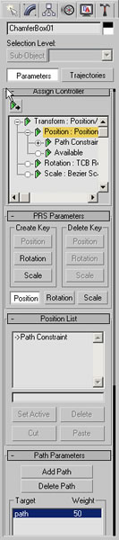
Figure 2: The Position List controller contains the Path Constraint and an Available slot.
4. In the Assign Controller rollout, highlight the Available slot, click the Assign Controller button and choose Noise Position from the dialog. Scrub the Frame Slider and the box will jump wildly in all directions as it travels along the path.
5. In the Noise Controller dialog set the X and Y Strength to 0 and change the Z Strength to 10. Check the >0 option for Z Strength to use only positive numbers, thus keeping the box from dropping below the path. Change Ramp in and Ramp out both to 1 to keep the box on the path for the first and last frames. See Figure 3.
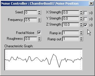
Figure 3: Adjust the Noise Properties for positive Z axis motion only and to keep the box on the path at the start and end frames.
Note: if you lose the Noise Controller dialog. Highlight Noise Position in the Motion panel and right-click, choose Properties from the menu to call the dialog back.
6. The next step will be to control the duration of the Noise so it occurs only while the box is on the flat, in this case from frame 24 to frame 74. You will need Track View for this. In the Graph Editors pull-down menu, choose Track View, Open Track View. Expand Objects, ChamferBox01, Transform, and Position to show the Range Bars for the Noise Position controller. Slide the left end of the Noise Position Range Bar to frame 24 and the right end to frame 74. See Figure 4. You may need to zoom in on the Track View for this step.
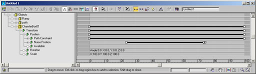
Figure 4: Adjust the Noise Position Range Bars to control the duration of the noise.
7. Scrub the Frame Slider and you will see the Noise action confined to the duration of the box on the flat area.
Tip: when you added a Noise Position controller to the Position List Available slot, another Available was added to the list. You can Copy and Paste the Noise Position in the Track View and adjust it’s Range Bar to get a second jumping at another point in time.
This technique could also be used on a camera to simulate the bounce of walking motion or going up and down stairs. You would just need to adjust the Frequency and Roughness settings in the Noise Controller properties dialog.
Using Trajectory Convert To:
Another handy feature that is hard to find in both VIZ and max is the ability to convert an animation trajectory into a spline that can be used as a Path Controller path or a loft path, for example.
In the VIZ 4 scene called ConvertTo.max I’ve animated a cylinder traveling along a W-shaped path. I used the standard method of turning on the Animate button then setting positions of the cylinder at frames 25, 50, 75, and 100. The cylinder uses the default Bezier Position controller, therefore adds the curvature and velocity changes throughout the animation.
Presume for a moment that it would be better if I had animated the cylinder traveling along a spline path so I could get better control of the velocity using Ease Curves. http://www.cgarchitect.com/upclose/article7_TB.asp.
It is not too late. This exercise will show you how to convert keyframe animation into a 2D spline that can be used like any other spline.
1. In the file ConvertTo.max, select the cylinder. The trajectory is showing because it was check on in the Properties menu accessed by right-clicking the object and switching to By Object instead of By Layer for the properties.
Note: it is always the Pivot Point of an object that is animated, therefore the trajectory shows the path of the pivot.
2. In the Motion panel, click the Trajectory button at the top of the panel. See Figure 5. The Sample Range setting determine the start and end times of the spline you want to create. The Sample Range indicates at which frames a vertex will be created for the new spline.
***Insert Figure 5 here: use ListCont05.jpg
Figure 5: Select the animated cylinder and click the Trajectories button in the Motion panel.
3. Using the default settings, click the Convert To button. A new spline called Shape01 is created that varies noticeably from the trajectory. See Figure 6.
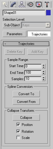
Figure 5: Click the Convert To button in the Trajectories rollout to create a new spline that varies from the original trajectory.
4. In the Trajectories rollout, increase Samples to 25 and click the Convert To button again. This time the new spline fits the trajectory much more closely because a vertex is created every 4 frames. These splines can be edited and used like any other spline at this point.
There is also a Convert From button that will allow you to create animation keys for an object by picking a spline in the scene.
Rotating Wheels with Wiring Parameters
Another question that come up often in my travels is “how do I animate wheels turning correctly as an object moves through the scene?” One method is to use Wiring Parameters with a mathematical formula to relate the turning of the wheel to the forward motion of a Dummy parent object.
In the scene WheelWiring.max I have set a Dummy on a path with Follow on. I then added the Ease Curve to make it go forward and backward over 100 frames. A cylinder is aligned with the Dummy and linked to it. The child (cylinder) must always go with it’s parent (Dummy) but can have it’s own actions (rotaton).
The cylinder has had its default rotation controller called TCB Rotation replace with a EulerXYZ rotation controller. This is necessary to allow access to each individual rotation axis as it’s only one that will react to the position changes of the Dummy.
1. In the file called WheelWiring, select the cylinder. From the Animation pull-down menu, choose Wire Parameters, Wire Parameters, Transform, Rotation, Y Rotation from the cascading menus. See Figure 6. Your cursor will then have a dotted line from the cylinder pivot.
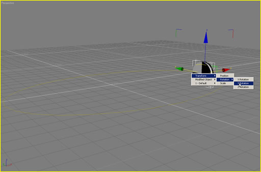
Figure 6: Choose Wire Parameters, Wire Parameters, Transform, Rotation, Y Rotation from the cascading menus.
2. While showing the dotted line, pick the Dummy and choose Transform, Position, Percent from the menus. See Figure 7. This will call up the Parameter Wiring dialog where you can define a mathematical relationship between the percent of the dummy on the path and the rotation of the cylinder.
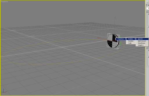
Figure 7: Pick the Dummy object and choose Transform, Position, Percent from the menus.
3. In the Parameter Wiring dialog, click the left pointing arrow between the hierarchical lists to cause the Dummy percent to control the Cylinder Y rotation. See Figure 8.
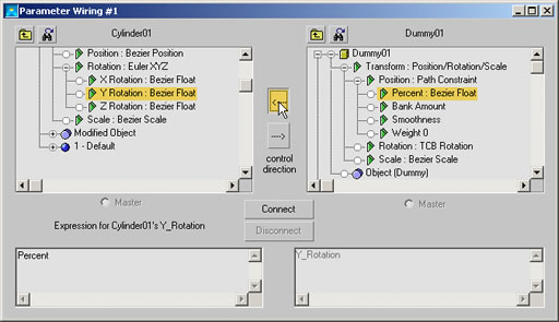
Figure 8: Click the left pointing arrow between the list windows to control the direction of the action.
4. The formula will be based on the Percent times the length of the path divided by the radius of the cylinder. ((Percent*41.3)/1). After entering the formula in the left field (See Figure 9), click the Connect button to wire the parameters.
Tip: the length of the elliptical path was found by selecting it and going to Utilities panel and clicking Measure.
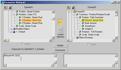
Figure 9: Enter the above formula in the left field and click the Connect button to complete the wiring
.
5. Drag the Frame Slider and you will see the cylinder rotate backward as it moves forward. To correct this, click the binocular button left of the cylinder name in the Parameter Wiring dialog and change the 1 in the formula to –1. Click the Update button. Dragging the Frame Slider now shows correct rotation.
Any animatible parameter can be wired to another for complex control. You will need to do a little research on the correct units used for each parameter, but the process is always the same.
Summary
You have learned a couple of uses of Animation Controllers and Wiring Parameters that may be helpful in some upcoming projects. But more importantly you may have a deeper insight to some of the things possible with VIZ and max and you will experiment to develop methods and ideas of your own.
Good luck and have fun.
DOWNLOAD MAX FILES HERE - 80KB
You must be logged in to post a comment. Login here.
About this article
Animation
visibility2.99 k
favorite_border0
mode_comment0