Tutorials
More Tips and Tricks

More Tips and Tricks
Ted Boardman tedb@tbmax.com http://www.tbmax.com
As some of you might have noticed, last months column was missing. It was an extra busy month with lots of traveling and finishing my newest book, 3ds max 6 Fundamentals by New Riders Publishing, that should be appearing in the books stores or available through my website around the New Year.
My travels took me to Helsinki, Finland; Tallinn, Estonia; and Rotterdam, Holland as well as a couple of training trips in the US. And yes, I managed to run into a 3ds maxer by coincidence on the streets of Tallinn. Douglas Triana, who is from Costa Rica and lives in Helsinki, and who I know from 3D Festival in Copenhagen was there for his birthday. Small world, huh?
By the way, I’m writing this column at the MGM Grand in Las Vegas where the 11th Autodesk® University is about to start this week. Hope to see many of you while I’m here.
Want a free computer?
Well, of course the answer is yes and, of course I don’t have one for you, but I will talk about a few things that you can do that could be the equivalent to getting a free computer. There are a few things you can do to streamline your workflow and to reduce computing overhead to free up RAM and processor cycles for better performance. We’ll look at some issues like File Linking in VIZ, shadow casting, and reflections and I’ll offer some suggestions that will be useful for both radiosity and scanline rendering.
File Linking
Someone on the Autodesk®VIZ forum recently was asking what equipment would be the best value for increasing rendering speed, new CPU, more RAM, or a new graphics card. The graphics card is not in the rendering loop at all so there is nothing you can do there to increase rendering speed. He already had 2 gigs of RAM and perhaps it would be worth getting more, RAM is relatively cheap these days. New CPU’s alone are seldom worth the price you pay as an upgrade, so save that money for a completely new computer.
I suggested he take a serious look at his modeling, lighting, and shadows to see where he could reduce overhead with a couple of the techniques I’ll mention in this column, but also make sure that he tried binding his scene if he was using File Linking from ADT or Acad.
Simply by binding this particular file the rendering time was cut in half. That is exactly the same as getting a free computer for the project. File Linking, by its very nature, needs large amounts of computing resources to keep track of everything and you should be certain that you really need the active file linking. You don’t need to give up file linking completely, in any case, just make a copy of the file and bind the copy for rendering. If you need to make changes you can go back to the original, edit it, copy again, and bind the new copy.
Binding the File Linking will be especially productive if your files are large enough to be taxing the current resources in your computer. If you have small files and lots of RAM, the savings may not be so dramatic, but hey, even 10 to 20 percent increase can be very helpful when you are up against deadlines…and it’s free!
Modeling
Another anecdote I’ll pass on from a recent training session is the case of a company that designs and builds modular homes and uses VIZ for presentations and marketing. They were getting some pretty good results, but wanted to get a better handle on efficient modeling, so I went in for a few days training.
The exterior example that we took for the class was a small single story house with minimal landscaping. The render times for a Daylight radiosity rendering was over 20 minutes, that’s after the radiosity calculations and is much too long, certainly for a two-day class.
I used Summary Info from the File pull-down menu to look through the scene for anything that might jump out at me. I soon found the front door handle at around 90,000 faces and three exterior lamps and around 40,000 faces each. Deleting those four objects from the scene brought the render times to around 4 minutes. A quick remodeling of the objects resulted no extra rendering time for the same quality of view. Again, the result was the equivalent of several free computers for that project.
Reflections
In many typical interior scenes, reflections can sometimes add considerable overhead to rendering time and often don’t look very convincing anyway. Let’s look at a couple of possibilities that might both save time and make the scene look better to the viewer.
Figure 1 shows a retail space in the process of being decorated. The lighting is “fakeosity”with 4 attenuated spotlights at the ceiling that are shadow casting, another attenuated spolight at the floor lighting the walls and ceiling to simulated bounced light from the floor. There is another Omni light the is place near the camera and is set to include only the stack of fabric covered chairs to boost them from the background. Remember, unless you are a lighting engineer, you will get better results by approaching lighting the way a photographer would, whether you are using Photometric or Standard lights.
The wood floor material is a Bricks map with a Wood map and with a Raytrace reflection map set to 50 percent Amount.
Figure 1: A retail space with a Raytrace map on the wood floor reflecting the scene.
The reflections do not look at all natural, but are overpowering and confusing. This scene took 20 seconds to render on a single P4 2.8gig machine.
One of the first things to do if you are using any Raytrace maps or Raytrace materials in your scene is to go to the Rendering pull-down menu, Raytrace Globals option and, in the Golbal Raytracer Settings change the Maximum Depth to 3 or 4. See Figure 2.
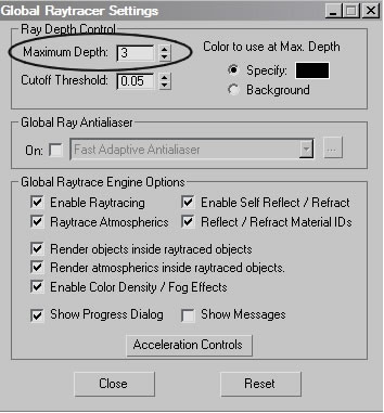
Figure 2: A good habit is to reduce the Maximum Depth of all Raytrace reflections.
This says that you can only have 3 inter-reflections, for example within a mirrored elevator car you would not see reflections to infinity, but the reflections would fade to a color after the third bounce. For most reflections the details become so small after 3 or 4 bounces that it is a waste of resources to calculate them. This will not give us any extra performance in the retail space because there are no other reflective surfaces for our floor to pick up, but it is generally a good habit to get into.
The next most important settings for Raytrace map reflections is the Attenuation of the reflections. Reflections are simply light and must follow the rules of physics. The reflecting surface is the light source and light decays based on the Inverse Square law. While it’s possible to set reflection decay to Inverse Square, a better solution that gives you more speed and control is to set attenuation to Exponential. This is found in the Falloff Type list in the Raytrace map Attenuation rollout of the Material Editor so is controllable on a per material basis. See Figure 3.
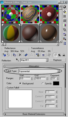
Figure 3: Set Raytrace map Attenuation to Exponential for speed and control
Using the default Ranges for the Exponential Falloff Type in this scene results in almost no reflections visible. Look at the floor just below the stack of chairs in Figure 4 to see a slight reflection that quickly falls off to nothing.

Figure 4: Default Exponential Falloff kills most reflections.
The render time has dropped from 20 seconds to 16 seconds, a substantial increase in productivity for such a simple scene, but the reflections are less than convincing, for sure.
In the Attenuation rollout you also have the option of setting ranges in system units, or in this case inches. The Start range is the distance from the reflecting surface that the reflection begins to attenuate. The End range is the point beyond which no reflections are calculated, therefore the faster rendering. The Exponent controls how quickly the cutoff is within the ranges.
Entering 100 in the Start field and 200 in the End field results in a reflection that is bright and strong at the base of objects but quickly dies out before reflecting any of the objects near the ceiling. Reducing the Exponent from 2 to 1 allows the reflection to extend slightly farther and increase the render time by only 1 second. See Figure 5.
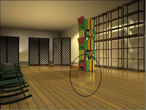
Figure 5: Adjusting the Exponential ranges and exponent settings results in more reflection that fades more convincingly. Render times dropped from 20 seconds to 17 seconds.
Raytrace material does not have the same Attenuation controls that a Raytrace map has, but in the Raytracer Controls rollout you can enter a Falloff End Distance amount and check Reflect (see Figure 6) to produce similar effects and production increases.
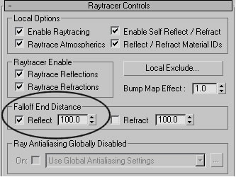
Figure 6: Raytrace material has a Falloff End Distance setting in Raytracer Controls to attenuate reflections.
Raytrace reflections can be blurred for a more convincing look, but usually at a severe hit to rendering times. You must first enable the Global Ray Antialiaser in the Global Raytracer Settings from Rendering, Raytrace Globals. Then in the Fast Adaptive Antialiaser dialog set the Blur and Defocus settings. Be forewarned however, that this is an expensive process. This can be set globally for all raytrace reflections or locally for a material but must always be enabled in the Raytrace Globals.
For this scene, a much cheaper method of blurring reflections for a more convincing look is to apply a Bump map to the material. For the wood floor a copy of the map that creates the color of the material can be dragged and dropped onto the Bump slot and the Bump Amount can be adjusted for the look you want. In Figure 7 the Bump Amount has been set to 5 to soften and blur the edges of the reflections, it is especially noticeable at the stack of chairs. The render time, however, has jumped from 17 seconds to 28 seconds, so make sure this is something you want to do.
Just for reference, the Global Ray Antialiaser blurring rendered at 44 seconds and look similar to this image.
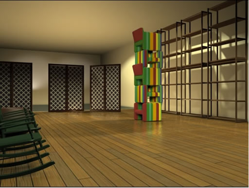
Figure 7: Adding a Bump map to the floor material softens and blurs the reflections while adding to render times.
Another important option in raytrace reflections is the ability to exclude objects from the Raytracer. Many objects in the scene are not really visible to a surface or have very little impact on the look of the final render but must still be calculated. Use the Exclude feature to bypass the calculations and enjoy potentially higher productivity.
Summary
Reflections are absolutely necessary to most scenes, especially interiors. You should always use attenuation both to increase productivity, but also because it usually makes a scene much more pleasing to the viewer’s eye.
Blurring raytrace reflections should be avoided if possible. Note, however, that Flat Mirror reflection map could be used on this floor to strike a good compromise with convincing reflections and blurring but there are restrictions that a Flat Mirror map must be used on coplanar coincident faces that reduce its usefulness.
Striking the right balance between the look you want and being productive is one of the toughest day-to-day decisions you face. However, if you do nothing to adjust your reflections it is guaranteed that you are wasting valuable computer resources, so learn to apply these tools and have fun with your newly found spare time!
Good luck
Ted
DOWNLOAD MAX FILE (213KB)
You must be logged in to post a comment. Login here.
About this article
More Tips and Tricks
visibility4.61 k
favorite_border1
mode_comment0