
Tutorials
Edge Editing

Edge Editing
Ted Boardman tedb@tbmax.com http://www.tbmax.com
Siggraph 2004 in Los Angeles has come and gone. You have probably read Jeff’s account at cgarchitect on the technical offerings on the show floor and the party scene after hours. My reasons for attending Siggraph are primarily for seeing old friends and acquaintances around the show floor and meeting many of you that read this column and my books over the years. I’m not usually in the market for any new software or equipment so the show floor tends to be a blur of vendors advertising mixed in with some interesting demo reels being played on the big screens throughout the exhibit hall. As for the party scene, I’m much too old for the late nights and especially the noise levels that discourage any kind of conversation. Years ago I would find myself nodding, with a stupid look on my face, as if I had really heard what the person inches from me had just yelled in my ear, so decided to give it all up for a quiet beer at the hotel bar.
On the Sunday before Siggraph I went to my favorite breakfast place, The Pantry on Figaroa, then walked up Wilshire Boulevard, through Macarthur Park to New Hampshire St, then back into town on a parallel street. From there I went by Frank Gehry’s new memorial to Frank Gehry, then out to the LA river and up to Union Station. There is something about sitting in Union Station that evokes a feeling of being in a place where history and hysteria have passed quietly together through the halls.
From Union Station it was a walk through Olivera Street, the old Mexican settlement, and down to the convention center to register and back to the hotel. I check my route on my mapping software to discover that my “walk” had covered just less than 13 miles. That called for a cold beer, for sure.
I do like downtown LA for it’s seedy edginess and mix of new and old buildings and neighborhoods.
The US holiday called Labor Day is this weekend and officially marks the end of summer, especially in the seacoast resort areas of New Hampshire and Maine. The weather has been struggling to show some signs of summer, but having only sporadic success. Saturday was very hot with extreme humidity that carried into Sunday morning. Around noon Sunday, the wind shifted out of the East and I had to get long pants and a flannel shirt to sit out on my porch.
Speaking of “edginess”, I’ve had a few client recently who had buildings with greenhouses attached as skylights or entry roofs and they agonized over the modeling during the design phase and were very disappointed when they had to make changes.
I’ll cover a workflow that will allow you to use several fundamental concepts in 3ds max and VIZ to keep the process flexible. As usual the example will be simple so you can focus on the process to adapt it to your needs.
The tools I’ll combine for flexibility are; Edge editing, Reference cloning, and Lattice modifier.
Edge Level Editing
Many times while working with Editable Mesh objects you have probably gone to sub-object Vertex or Polygon to make changes to the model. However, I find that few people have investigated Edge sub-object level editing and the options it offers for making changes that would otherwise be difficult.
We will start with a simple roof in VIZ 4 so that the file is accessible to most versions of max and viz.
If you open the file called Greenhouse_VIZ4_base.max you will find a rectangle called GREENHOUSE_GLAZING with a Bevel Profile modifier applied that uses the greenhouse_profile 2D shape to create a simple hip roof with fascia, soffits, and trim. This is the basic form on which the greenhouse is to be built.
In the Perspective viewport, the Edged Faces option has been turned on so you can see the wireframe and shaded object at the same time. See Figure 1.
Figure 1: Basic hip roof created with Bevel Profile modifier. Edged Faces enabled in Perspective viewport.
This is the glazing of the greenhouse and you will need the greenhouse frame to hold it up. You will use Cloning to create a Reference clone of the roof. This sets up a one-way connection so if the glazing is modified, the frame will change, as well. However, if you modify the frame it does not pass the changes back to the glazing.
TIP: If you made an Instance Clone you have a two-way connection and changing one object would change the other to be exactly the same which won’t work for this purpose.
Select GREENHOUSE_GLAZING in the Perspective viewport and, from the Edit pull-down menu, choose Clone. In the Clone Options dialog, check the Reference radio button and name the new object GREENHOUSE_FRAME. See Figure 2. Click OK.
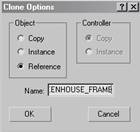
Figure 2: Make a Reference clone and name the object GREENHOUSE_FRAME.
In the Modify panel, click the small color swatch next to the object name and change the color to a dark blue to make it more visible.
With GREENHOUSE_FRAME selected, click the Modifier List and choose Lattice modifier from the list. The Lattice modifier turns the vertices of the object into Joints and the visible edges of the object into Struts. I stress the term visible because you will use that fact to control the frame.
In the Modify panel, Parameters rollout, choose Struts Only from Edges for this frame. The Joints can increase the file size enormously and should only be used when necessary. Change the Struts Radius to 0’3” and set the Sides to 6. This frame would certainly not be sufficient for such a large roof but you will not adjust the frame itself, rather you will work on the original glazing object. This will keep both objects in synchronization with each other.
Select GREENHOUSE_GLAZING and greenhouse_profile. In the Tools pull-down menu, choose Isolation Selection to work on just the glazing object. You will add horizontal framing members to the greenhouse by modifying the 2D profile that defines both the glazing and the frame.
Select greenhouse_profile and, in the Modify panel, go to sub-object Segment. Select the long segment that defines the roof plane. In the Geometry rollout, enter 6 in the Divide field then pick the Divide button. Six new edges become visible on all the roof planes. See Figure 3. Exit sub-object mode.
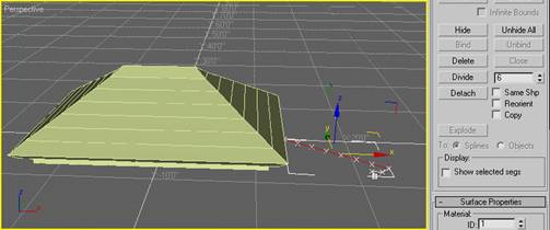
Figure 3: Using Divide at sub-object Segment on the profile adds visible edges to the roof.
You still need vertical struts that will carry the roof load to the walls. Editing the glazing rectangle can do this. Select GREENHOUSE_GLAZING. In the Modify panel, expand Editable Spline in the stack and choose Segment sub-object level. Select the two long segments of the rectangle and click the Divide button to add 6 vertices to the segments.
Select the two short segments, enter 4 in the Divide field, and click the Divide button. This adds 4 new vertices to the short segments. Exit sub-object mode and return to the top of the Modifier Stack. The glazing now has vertical as well as horizontal visible edges. See Figure 4.
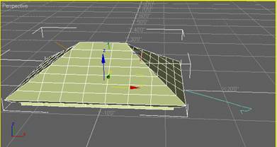
Figure 4: Using Divide on the Segments of the rectangle creates vertical visible edges.
Click the Exit Isolation button in the Isolated Selection dialog to unhide the frame. It now has struts to match the new visible edges.
Note: This exercise has not been mathematically calculated to have correct sizes and dimension, so the struts may not make a perfect greenhouse. It is the process that is important to focus on.
You have created a fairly complex greenhouse with only two 2D shapes and a couple of modifiers but, chances are, it would fall over without any diagonal bracing to stiffen it. All faces in a mesh object are triangular so you will take advantage of that to add some bracing by editing the glazing mesh. Select GREENHOUSE_GLAZING and right-click on it. In the Quad menu, choose Properties. In the Object Properties dialog, Display Properties area, change to By Object (VIZ only) and clear the Edges Only option. Click OK. This show both visible and invisible edges of the mesh object. See Figure 5.
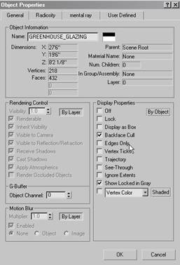
Figure 5: For GREENHOUSE_GLAZING, change the Display Properties to turn off Edges Only mode to make all edges visible in the viewports.
TIP: The edges will be easier to see if you change the color of the glazing to a darker color.
In the Modify panel, add an Edit Mesh modifier, expand it, and choose Edge sub-object level. In the Selection rollout, check Ignore Backfacing to avoid selecting edges at the back of the mesh and choose the dotted diagonal edges in the third row from the bottom to highlight them red. In the Surface Properties rollout, click the Visible button to make the edges visible and they will appear as struts in the frame. See Figure 6.
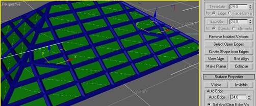
Figure 6: Using Edit Mesh modifier to make edges visible in the glazing creates struts in the frame.
In the Edit Geometry rollout, click the Turn button and pick the edge that defines the brace on the left side. Turn flips the diagonal edge to face the other direction. See Figure 7.
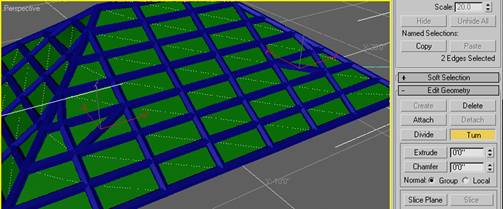
Figure 7: Use the Turn tool to flip individual edges.
Try editing some other braces then exit sub-object mode to return to the top of Edit Mesh modifier. Again, you have created a complex object that would be a sufficiently convincing greenhouse with the right materials and lighting. The object is efficient and very easy to edit.
For one more example of a potential workflow, remove the Edit Mesh modifier that you just adjusted and return to the Bevel Profile modifier level. Click the Pick Profile button, hit the H key, and double-click greenhouse_profile_curve in the list to replace the basic hip roof profile with one that is curved. It would be possible to have many profiles created to swap out at any time for quick variations for the client. See Figure 8.
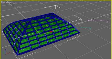
Figure 8: By changing the profile in the Bevel Profile modifier you can quickly create new variations for the greenhouse.
Summary
It is the workflow and the combination of tools and modifiers used here that you should be paying attention to. It just happens that the example is a greenhouse, but the techniques are not limited to that example. Take the time to experiment and develop objects you use in your daily work that may be similar. The expansion joints on a building façade come to mind.
The point is you have created complexity from very simple objects that allow you to modify your objects very quickly and efficiently. You can open the file called Greenhouse_VIZ4_complete.max to see the example created here.
Good luck and have fun.
Ted
You must be logged in to post a comment. Login here.
About this article
Edge Editing
visibility3.81 k
favorite_border0
mode_comment0