
Tutorials
Tips

Tips
Ted Boardman tedb@tbmax.com http://www.tbmax.com
Just as I suspected, the cold spring weather is replaced by hot, muggy, or hot and muggy weather with plenty of coastal fog with not much of a break in sight. My recent travels have taken me up to Regina, Saskatchewan where I was expecting to be hot and it turned out to be 90 degrees F and dry; absolutely perfect weather.
By the time you read this column, Siggraph will have come and gone in San Diego and, hopefully, I will have met some of you personally and had a chance to visit with some old friends that I only get to see at the major trade shows.
If you won’t make it to Siggraph this year I’d encourage you to start planning for next years show. I’ve always encouraged people in the “technical’ fields to get to Siggraph at least once even though there has been much specifically aimed toward the entertainment industry in past years. That’s changing. While there have always been architects and engineers at the show, it took Jeff Mottle’s initiative to provide a gathering place to facilitate those personal contacts that are really the best reason to attend trade shows to begin with.
There are also a lot of important research and trends that come from the academic and entertainment community that will impact your future directions and decisions and Siggraph is the best place to see those first hand.
I’m going to use this column to cover some tips and tricks and little things that don’t always fit in columns with a specific theme and are sometimes overlooked. The screen captures will be from 3ds max 5, but VIZ 4 will be the same or similar screen while the same functionality should be found in VIZ 3.
Modeling
Shape Check and Interpolation for ShapeMerge
Have you tried using the ShapeMerge Compound Object to cut new edges in mesh objects and found it to be a frustrating process, especially if the splines are imported from other software?
Given the fact that ShapeMerge is a form of Boolean operation, it’s not so surprising that it might give us the fits occasionally, but there are a couple of things you can do to make the process more reliable.
The majority of problems are caused by invalid or overly complex curved 2D shapes. Invalid 2D shapes generally self-intersect, although the loop may be so small it is impossible to see even after zooming in close to the suspected problem area. Of course, in order to create a shape that will fail, the effect must be exaggerated as I don’t happen to have a bad shape on hand. These problems can be detected with a utility called Shape Check.
If you pick on the Utilities panel button, then click the More button, you can choose Shape Check from the Utilities list. See Figure 1.
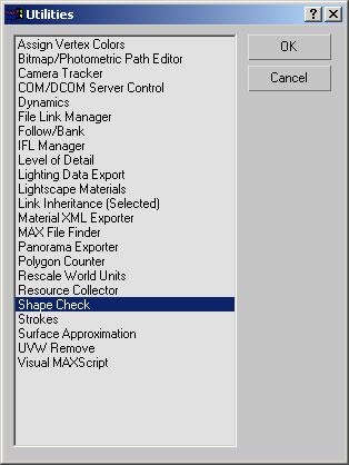
Figure 1: Clicking the Utilities panel button, then More, will allow you to choose Shape Check from the list of utilities.
If you pick the Pick Shape button in the new Shape Check rollout and pick a 2D shape in the viewports you will see a message of either Shape OK or, if there is a problem, Shape Self-Intersects. See Figure 2.
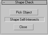
Figure 2: Picking a problem 2D shape in the scene shows the message Shape Self-Intersects.
Another indicator of where the problems on the shape are will be red boxes in the viewports around the areas that need to be fixed. See Figure 3.
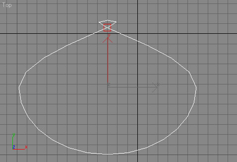
Figure 3: Red boxes show in the viewports indicating problems found by Shape Check.
Shape Check only identifies problems but does not fix them. You can usually fix the problem by going into sub-object Vertex mode, selecting the Vertex, right-clicking on the Vertex, and converting the tangency to Corner type, found in the Quad menu that pops up. You can then right-click on the Vertex again and switch to Smooth, then again to switch to Bezier or Bezier Corner, depending on the editing you need to perform. Because switch to Corner, Smooth, and Bezier will change the curvature of the original shape somewhat it is almost always necessary to make some adjustments.
Another fix for problem shapes can be to lower the Interpolation values of the splines. If a ShapeMerge operation fails and Shape Check doesn’t identify any problems try reducing the Interpolation values.
Spline Interpolation steps are intermediate steps between vertices that define curvature in the segments. The can be found in the Modifier panel, at the Shape level, in the Interpolation rollout. See Figure 4.
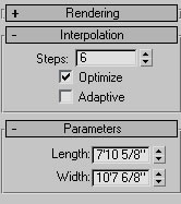
Figure 4: Interpolation Steps can be adjusted in the Interpolation rollout of the Modify panel when a 2D shape is selected.
Reducing the Interpolation steps uses fewer curvature steps between vertices simplifying the shape and increasing the chances of a successful ShapeMerge operation. See Figure 5 for the result of reducing the Interpolation of an Ellipse shape from the default 6 to 2. The effect can be seen clearly on the ellipse itself and the 3D mesh resulting from extruding the ellipse shape.
Figure 5: The effect of reducing the Interpolation Steps from 6 to 2 on the 2D shape and 3D geometry created from the shape.
This example is illustrative of the effect only, but reducing the Interpolation Steps of failed ShapeMerge shapes can often fix any problems.
Soft Selection
Another handy tool within max and VIZ is Soft Selections. It allows you to select specific sub-objects, vertices for example, and have a weighted effect on surrounding vertices. The soft selection is indicated by color-coding the vertices Red vertices are affected by the full amount of the action, a move or a modifier, for example, orange vertices are affected somewhat less, yellow less yet, and blue vertices are not affected at all.
Soft Selections are activated by checking the Use Soft Selection option in the Soft Selection rollout then by adjusting the settings for the desired area of influence. See Figure 6.
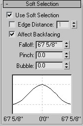
Figure 6: Soft Selection rollout in the Modify panel
Figure 7 shows an example of using Soft Selection when moving vertices of a Plane. Several vertices along the back edge of the plane were selected and the Falloff distance was set to include about 2/3 of the planes vertices. When the vertices were moved in the Z-axis the weighting effect is clearly seen in the viewports.
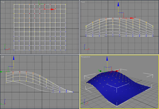
Figure 7: By applying Soft Selections and moving vertices the deformation to the surface is much smoother and rounded as opposed to just a spiking effect you would get without Soft Selections.
Another, more flexible, method of using Soft Selections is with the Vol. Select modifier (Volume Select). With Vol.Select you can choose to use other mesh objects or maps to define the area of selection with Soft Selection as an option.
In Figure 8 you can see a Plane with Vol.Select set to use a Noise maps. The grayscale values of the pixels in the map determine which vertices are affected. White pixels affect the most, black pixels have no effect, and gray pixels are some level in between. In this example a Noise modifier has been applied above the Vol.Select modifier to modify the surface only in specific areas.
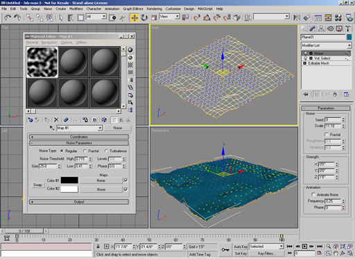
Figure 8: Vol.Select modifier with a Noise map determining the selection weighting and a Noise modifier to move the vertices in a soft manner.
Materials and lighting
Textured Glass
I often see the question about how to reproduce the look of texture glass in the forums and in classes I teach.
A method I have found convincing and effective is with the use of a Bump map and a Thin Wall Refraction map. Figure 9 shows the Material Editor, Map Navigator, and rendered image of an example of the effect.
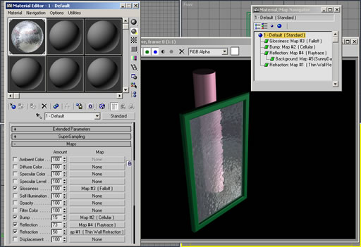
Figure 9: The combination of Bump map and Thin Wall Refraction map can be used to create the effect of textured glass.
In this example I used the Cellular map to create the distorted refractions in the glass. A black and white Speckle map at a very small size setting can create a more sandblasted effect.
Opacity is not set for this material but is determined by the Amount setting for Refraction. In this example, a setting of 50 gives the glass a milky look.
Other maps have been used in this example for Glossiness and Reflection to enhance the look of the glass interacting with the simple lighting in the scene.
Experiment with different settings and maps to create unusual effects of your own.
Raytrace Attenuation
Another small option that can make your images more convincing is Raytrace Reflection Attenuation. In this example I will use the Raytrace map within a Standard material, but the Raytrace material has a similar setting called Falloff End Distance found in the Raytracer Controls rollout.
Figure 10 shows the Raytrace map Attenuation rollout. The Falloff Type is set to Exponential, which is the most efficient method and offers controls for the look you want. The Ranges tell reflections when to start attenuating and when to be completely attenuated and the Exponent setting adjusts how quickly the attenuation cuts off between those ranges.
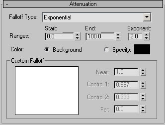
Figure 10: Attenuation can be adjusted in the Raytrace reflection map’s Attenuation rollout.
Figure 11 shows an example of a simple bathroom scene. The floor in the left image has no reflection Attenuation and the right image has the default Attenuation settings. The attenuated reflections are apparent but not so overbearing in the scene, lending a more convincing appearance.
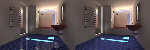
Figure 11: Left image, no attenuation used on the floor material, right image has Exponential attenuation with the default settings.
Miscellaneous
Numeric Expression Evaluator
An often-overlooked tool that has been in max and VIZ for quite a while is the powerful Numeric Expression Evaluator that can be used for complex calculations in any numeric field.
Math functions as complex as Hyperbolic trigonometry functions (don’t ask me) can be entered and calculated. The calculations follow common rules for nesting within parenthesis for control of the flow.
Highlighting any numeric field and typing Ctrl N accesses the Numeric Expression Evaluator. In Figure 12 I show an example of an expression entered for the radius of a sphere. The expression in this example doesn’t mean anything but is just used to show some of the functionality.
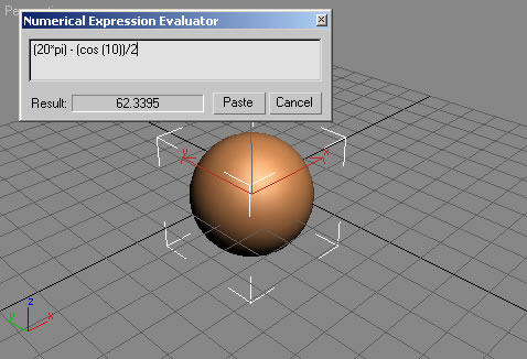
Figure 12: Complex expressions can be entered in any numeric field with the Numeric Expression Evaluator.
Named Selection Sets
A very powerful option in max and VIZ is the Named Selection sets that can be used to organize collections of objects or sub-objects to increase productivity. They are simple to use and have none of the odd behavior associated with Groups.
Named Selection Sets are found in the max Main toolbar, but the menu must be opened in VIZ by right-click an empty space in the Main toolbar and check the Name Selection Sets option.
When you have objects or sub-objects selections in the scene, you can enter a name and press Enter. The Enter key is very important to make sure the name is registered as a Named Selection Set.
You can also access the Edit Named Selection Set dialog (see Figure 13) from the Main toolbar in max or from the Edit pull-down menu in max or VIZ.
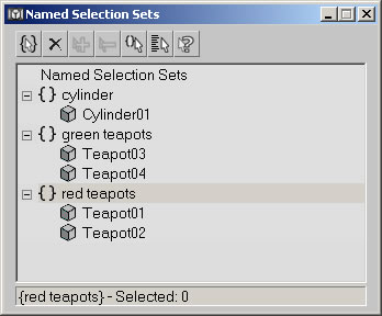
Figure 13: Edit Named Selection Sets dialog
You can select objects in the sets through the toolbar pop-up list, or through the pop-up list found in the lower right corner of the Select By Name dialog.
Even more powerful is the ability to name sub-object selections which, by the way, only will show in the toolbar pop-up list while you are in the appropriate sub-object mode. Figure 14 shows an example of a Named Selection Set comprised of the upper vertices of a cylinder in Vertex sub-object mode.
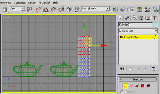
Figure 14: For sub-object selections sets you must be in the appropriate sub-object mode.
Very often you will need to retrieve a selection at sub-object level after you have edited the mesh only to discover that the selection is virtually impossible to recreate due to changes in topology. Be on the safe side and create a Named Selection Sets as soon as you have selected at the sub-object level.
Summary
These are a couple of little tips that can sometimes make a big difference in your productivity when you practice a little to make them an automatic part of your daily workflow.
Each one in itself is no big deal, but used regularly, the combination of the small things can make an impact on productivity.
Hopefully, by the time you read this column I will have met many of you at Siggraph.
Good luck and have fun.
Ted
You must be logged in to post a comment. Login here.